 | Home > Technical (L322) > P040D-00 (2F) EGR temperature sensor replacement |
 
|
|
|
| GGDR Member Since: 26 Nov 2016 Location: London Posts: 3552  
|
Following my exploits here: https://www.fullfatrr.com/forum/topic48131.html
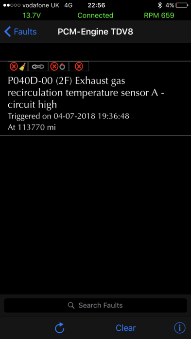
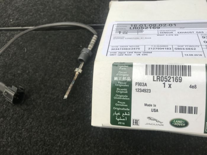
This error is common on the 2011-2012 4.4TDV8 L322 and the early SDV8 L405s. At some point the part was revised and that seems to have dealt with it. The part below is the revised part fyi. You can read in the above thread the full journey to discovery, but in summary the main trap that many including some indy mechanics, (possibly even some MD’s) fall into is that the error code says EGR sensor. So they head there. But Sensor A is nowhere near the EGR, it’s on the NS exhaust manifold. This has led to many changing the sensor on the EGR (sensor B), having the error return and people writing this off as a "ghost" code. So they leave this error present under the "they all do that" category. Others have changed their whole EGR. Possibly unnecessarily. This is a hard hard job due to (lack of) access.. But this guide will make it possible, and take less time than I did. I had a ton of trial and error. It was interesting to read a while back that CamTechCraig got this done on his 405 by a MD and they screwed it up. So size nines at the ready, let’s get started: Part, Tools and Prep You will need a replacement sensor - this part:
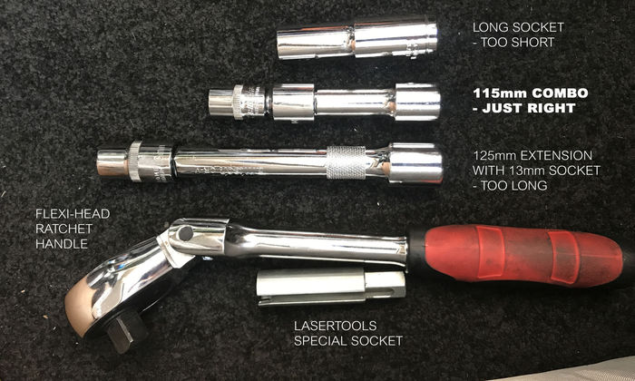
You’ll also need a special tool. There are two available, one is JLR (12-sided) and the other is by Laser tools (6-sided). I’d strongly recommend the Laser tools one as the 6-on-6 reduces the risk of rounding. More on that in a minute. Laser tools Exhaust Gas Temperature Sensor Socket Jaguar & Land Rover Part No. 6850 https://www.lasertools.co.uk/product/6850 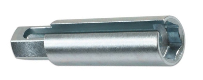
Other tools: You'll need a Flexi Head Ratchet handle (I got this one https://www.ebay.co.uk/itm/112745398503 )
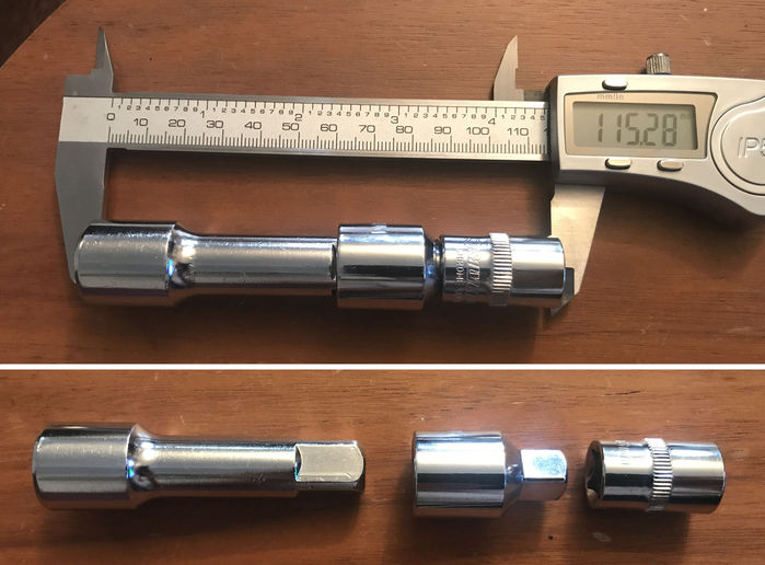
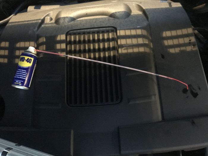
You'll also need a specific combination of 13mm socket with an extension. This needs to be more or less 115mm long. I achieved this with: 1 x 3/8 drive 13mm socket 1 x 3/8 to 1/2 adaptor 1 x 1/2 drive 75mm short extension bar IMPORTANT: I tried many many combinations and strongly suggest you order this combo as it works in “the hole” with the Flexi Head ratchet handle. EDIT: This worked for me however a couple of Others have reported a very long extension bar can work too. WD40 with a cobbled long delivery tube. I used small-bore drinking straws 3-4 connected together. Like this:
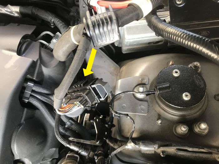
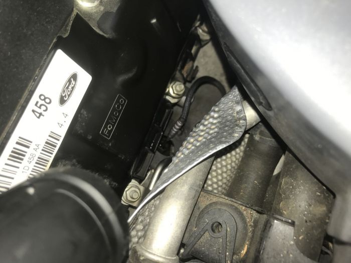
8mm ring spanner, best to use a ratchet version. Suggest dropping the car into access mode at this point. It will increase your reach down into ‘the hole’/ Step one: Locate and identify the sensor. It’s on the NS exhaust manifold. For now I’d not remove anything. You just need to sight it. It’s down a kind of vertical shaft space. “the hole”. You can get one hand in there, but not two. You can look with a torch however when one hand/arm is down there, you can no longer see down the hole. Advance warning: the hole will drive you mad. The hole is down here where the yellow arrow points:
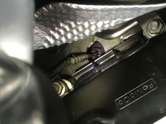
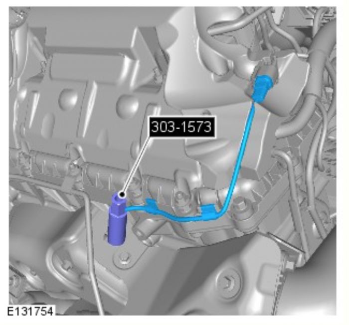
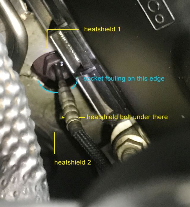
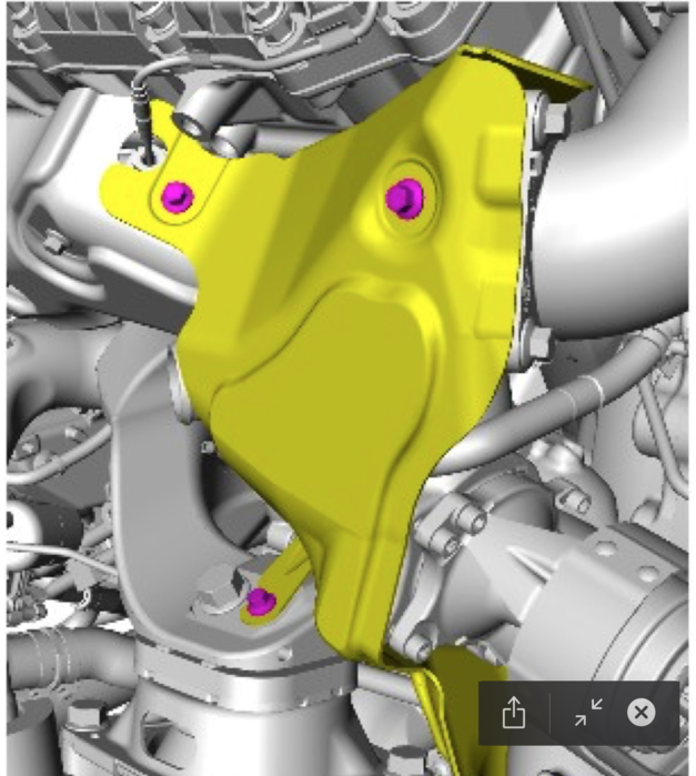
This last pic from the WM shows the socket on the sensor. Once you can see you need to get it lubed. Feed down your long tube of WD40 (or preferred penetrating oil) and douse. This is not a once only task, my STRONG RECOMMENDATION is to repeat daily for as many days as you want. Doing this is money in the bank. And BTW driving / heating the engine won’t affect this process. Why is this important? Be aware there the risk with this job of rounding the sensor nut. ] If it rounds, like another member you will have to replace the exhaust manifold. And that's a dark place you don't want to go to. So you want to do everything you can to reduce this risk. As far as I can say, there are two things you can do to mitigate this risk: - One is the regular, repeated pre-spraying with WD40 over many days. - The other is to use the 6-sided tool. The sensor takes extreme heat sitting there on the exhaust manifold. My sensor, baked in to it’s home for over 100,000 miles came loose almost immediately thanks to having daily WD40 sprays for a week. Others have not been so lucky. If you round the nut you have a HUGE job of removing the exhaust manifold. Step Two Remove air box. Remove battery surround Feel along the cable from the sensor, unclipping it as you will feel/follow the cable to find the connector towards the back of the engine. Undo connector. Spray WD40 on the sensor again. Step Three The Exhaust Shields. These are bastards. There are two that overlap right over the sensor. The problem is that they have been designed poorly and whilst have an access opening around the sensor, the opening is just a little too small to get a socket over the nut and they have to be completely moved/bent out of the way before you can get a socket on the sensor. This pic shows the two shields in place. Ignore blue text in image.
FYI I wasted many hours trying to figure a way of getting that opening just a bit bigger but trust me, you have to get the shield out of the way completely. Their overlapping layout doesn't really show well in the above pic so I did a quick diagram: 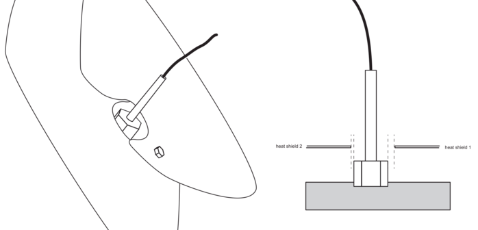
You need to feel for two retaining bolts 8mm on the heat sheild going from the sensor heading towards the firewall. Use a ratchet ring spinner to undo them. You can’t see them, you have to find and undo them by feel. It’s also a one hand job that’s why the ratchet ring spanner is best, it reduces the risk of those bolts falling - I kept one finger over the head of the bolt while undoing. One bolt is 25-30mm right below the sensor (but completely out of sight) and the second you’ll have to feel along the shield towards the firewall until you feel it. You'll be doing this all completely blind. Here's another angle of the heat shield (you can't see it like this ever):
Once these two upper bolts are off (I only undid the top two) you can bend and swivel the shield(s) off and away from the sensor. I bent mine quite a lot but they’re aluminium and bent back all fine after. Now's a good time to spray WD40 on the sensor again. Step Four. Snip the cable to the old sensor right on the end nearest the sensor end with some cutters. You’ll be binning this sensor anyway and it means you can fit the socket on and rotate it 360°. Step Five; Ok now you can fit the 13mm socket onto and over the sensor nut. You should feel with your fingers that the socket’s gone down right over the hex faces of the nut. Check again. You want to be absolutely sure it't engaged down fully on the nut before you start pulling on it anti-clock. You can leave the 13mm socket in place and attach your 115mm long extension combo, and the flex-head ratchet and go ahead and try a bit of a turn of the nut. With daily WD40 for a week prior, mine cracked loose easily. I think garages would not be able to practically afford the long WD40 prep I was able to do and I am guessing that is why they hit problems. Just a note here, you don't use the special socket for removal because it may open up having an open side. If it cracks loose then keep turning and once the nut is would all the way off, the sensor, with a wiggle the sensor should pull out. I mistakenly broke my sensor stem and I had a few hours trying to extract the actual sensor once the nut was off. So learn from me and clipping the cable as above will leave a stem and that is what you need. Hang onto the nut btw. And also fyi the sensor sits on a lip so it won’t fall into the manifold. Step Six: There’ll be a bit or crud around the thread in the sensor hole so you need to clean the thread out. I used pipe cleaners, and also a little bale of 5-6 cotton buds. Insert into the sensor hole and wind anti-clock. Repeat until you feel it’s clean. Now take the nut (just the nut) from the old sensor and you want to wind that into the thread in and out to make sure it’s clean. The reason for this, and the cleaning is that if you cross-thread the new sensor you will be in as bad a place as rounding the nut removing the old one. Hand winding that in an out is recommended. Clean again if need be. Step Seven: Carefully feed the new sensor into the hole. With that thread cleaned, you should be able to hand wind that nut in a fair bit. You want to be 100000% sure it’s engaged on the thread correctly. Even with a clean thread, mine was fiddly to engage on the thread. Once you’re sure, Grab the special socket and this should allow you to wind it in by hand another few turns. Oh, and if you want to put a little anti-sieze grease on the thread, it’s a nice idea for the next guy. The special socket has a slot to accommodate the cable. The cable means you can only safely make about one-eighth turns on the ratchet. So take your time and check the cable is not twisting after each eighth turn. You’ll need to lift the socket off the sensor nut, rotate it backwards, re-check the cable is not trapped and turn again. So it's not quick but doing this slowly and carefully will prevent damage to the cable. Repeat many times until tight. The torque setting is 32nm but challenge is can you get a torque wrench in there? Not likely. Suggest you turn another nut to that torque and ‘feel match’. Not ideal but the only ratchet arm I could get in the hole was the flexi-head. Step Eight: Re-fit everything else: Clip the cable on it’s route to the connector and then plug it in. Re-fit heat shields. you’ll need to carefully bend the sheilds to get them back into position kind of over the sensor, then bend them flat. Re-fit the two 8mm bolts. Take your time. Rushing can lead to dropping one of the 8mm bolts and good luck finding it! Refit air box and battery surround. Fire up the engine, and the IIDTool and run an error scan. All being well you’ll get this:
Kettle on. Hopefully these all make sense. Fire me any questions if you need. Good luck! Cheers, Greg - - - - - - - - - - - - - - - - - - - - - - - - - - - - - - - - - - - - - - - - - - 2011 Vogue SE 4.4 with lots of toys in Stornaway Last edited by GGDR on 14th Jun 2020 7:55am. Edited 18 times in total |
||||||||||||||||||||||||||
|

| Joe90 Member Since: 29 Apr 2010 Location: Hampshire Posts: 6419 
|
Nice work ggdr |
||
|
| mpirie Member Since: 26 Jun 2012 Location: In the Highlands Posts: 908  
|
Well done ggdr, i'm sure Stan will find a slot in the Wiki for this fix. |
||
|

| stan Site Moderator Member Since: 13 Jul 2010 Location: a moderate moderated moderator moderating moderately in moderation Posts: 35648
|
a lot of work has gone into this write up and duly wiki'fied , thank you greg .. |
||
|
| Bushy30 Member Since: 03 Jun 2018 Location: Powys Posts: 1099 
|
Genius Sir |
||
|
| mpirie Member Since: 26 Jun 2012 Location: In the Highlands Posts: 908
|
I wonder if there are any JLR main dealer "mechanics/technicians" who use the information and techniques collected on this forum in their daily repairs and servicing?
|
||
|
| GGDR Member Since: 26 Nov 2016 Location: London Posts: 3552
|
Thanks for your kind words chaps. |
||
|
| DrRob Member Since: 16 Apr 2015 Location: Petersfield, Hampshire Posts: 4332 
|
I've enquired to Rob at Rovertune about doing this. I have a reasonable quote and will be booking it in sometime in March. I'm not going to post the exact figure as that would be unfair to Rob but it starts with a number that rhymes with tree... |
||
|
| GGDR Member Since: 26 Nov 2016 Location: London Posts: 3552
|
Just a note to clarify that these instructions relate to the L322.
|
||
|
| j9ffy Member Since: 27 Mar 2018 Location: Indre Posts: 33  
|
GGDR - thanks a ton for this. Not only has your excellent research helped me to identify the underlying issue that generates the "mystery" fault code, but your huge determination to complete the job and share your experience has helped me enormously. Even with this, it's still taken me a full day to remove the sensor... now just awaiting the special tool before I can fit the new sensor... I've done plenty of spannering in my time but this job takes the biscuit - I just wish I had smaller hands.
|
||
|
| Corsica Member Since: 03 Jan 2019 Location: Corse Posts: 50
|
Hello Guys
|
||
|
| GGDR Member Since: 26 Nov 2016 Location: London Posts: 3552
|
j9ffy - great effort! I do think you may have had less trouble using the ratchet arm I got, but you've also proved it's possible with something else! Well done. And good luck getting the new one in.
|
||
|
| Corsica Member Since: 03 Jan 2019 Location: Corse Posts: 50
|
the problem is to know if when we cut the wire of the sensor we have to be sure if it won’t create an erreur indicator of engine and make it Turn in restriction mode... |
||
|
| j9ffy Member Since: 27 Mar 2018 Location: Indre Posts: 33
|
This shouldn't be a problem as the wire is cut after disconnecting the sensor, and the vehicle should remain off until the new sensor is fitted. Even so, others here (Tore2ls, I think) have sensibly fitted the new sensor in place of the old one (ie connected the new sensor after disconnecting the old one from the wiring harness, but before extracting it from the manifold) to check that the fault clears with a sensor that is working and that the new sensor is not a faulty item before fitting ( I didn't do this but probably should have if I were being thorough |
||
|

|
|
| All times are GMT + 1 Hour |
< Previous Topic | Next Topic > |
Posting Rules
|
Site Copyright © 2006-2025 Futuranet Ltd & Martin Lewis
![]()
