 | Home > Maintenance & Mods (L322) > ZF 5HP24 Transmission rebuild - How To ? It begins..... |
 
|
|
|
| Haylands Member Since: 04 Mar 2014 Location: East Yorkshire Posts: 8542  
|
Been reading this with interest and must say you have the patience of a saint and you now must be very good at getting the box in and out... lets hope these last few niggles can be sorted easily...
|
||
|
| andrew.aa Member Since: 16 Aug 2011 Location: PERUGIA Posts: 102  
|
I unscrewed the TC bolts, half turn to the converter, and screwed the four bolts.
|
||
|

| andrew.aa Member Since: 16 Aug 2011 Location: PERUGIA Posts: 102
|
today started car and put reverse, and the same noise as a rattle, and received immediately failsafe message.
|
||
|
| fulmjdun Member Since: 30 Sep 2014 Location: Bristol Posts: 5 
|
Hello all, I belong on the list of people crazy enough to have a go at rebuilding the 5HP24 autobox, so have read this and other posts with interest and immense admiration and respect for those who have given their time and knowledge freely - but am now getting to the point of pulling hair out!
|
||
|
| RRPhil Member Since: 22 Aug 2011 Location: Blackburn, Lancashire Posts: 1000
|
A faulty sprag OWC would certainly cause problems with 1st gear, but not 2nd.
|
||
|
| fulmjdun Member Since: 30 Sep 2014 Location: Bristol Posts: 5
|
Ah, my profile was out of date, my RR is now a 4.4 V8 Autobiography, but all other details the same!
|
||
|
| RRPhil Member Since: 22 Aug 2011 Location: Blackburn, Lancashire Posts: 1000
|
Yes, on the 1-2 upshift the E brake/clutch is applied and it takes over from the 1st gear sprag. The A clutch remains applied throughout as it�s used in 1st, 2nd, 3rd & 4th gears. 2nd gear is the only ratio which uses the E brake/clutch.
|
||
|
| fulmjdun Member Since: 30 Sep 2014 Location: Bristol Posts: 5
|
Phil,
|
||||
|
| RRPhil Member Since: 22 Aug 2011 Location: Blackburn, Lancashire Posts: 1000
|
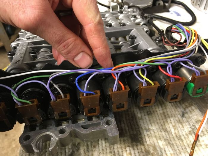
Your wiring harness is correct and the workshop manual description is wrong. Pins 12 & 16 are both 12v power supplies for the solenoids. The wiring should be connected like this :
or, in other words :
Might also be worth pointing out that the wire colours described in the manual are for the wires from the ECU to the 16-pin plug on the vehicle. These wires are coloured differently to those in the wiring harness between the 16-pin plug and the solenoids in the transmission, as otherwise this would be far too easy. "Also, on the output shaft, are there o-rings that fit in the last two grooves? I have the snap ring in that has the park wheel resting on it, seems like there should be some o-rings there to stop oil flowing past the spline." The first groove (nearest the front of the transmission) is for the snap ring, which provides the abutment for the park lock wheel, then the next groove rearwards is for an O-ring which, as you say, is to prevent fluid tracking up the spline. There appears to be a third �groove� in the output shaft but this is just an undercut for the machine that cut the spline to runout into. The O-ring is Land Rover part number TYX000100, ZF part no. 0734 313 181 and it�s actually an identical size to the oil filter O-ring. I have loads of new ones in stock if you struggle to get hold of one.
Phil Admin note: this post has had its images recovered from a money grabbing photo hosting site and reinstated |
||||||||||
|


| RRPhil Member Since: 22 Aug 2011 Location: Blackburn, Lancashire Posts: 1000
|
By the way, just curious, but have you removed the little black tubular sleeves holding the wires together between each solenoid connector or is that how you found it? The PTC sensor really shouldn�t be left to dangle like that, it should be held in by the sleeving.
In case you�re worried about the broken connector, I can supply these too. Phil Admin note: this post has had its images recovered from a money grabbing photo hosting site and reinstated |
||||
|

| fulmjdun Member Since: 30 Sep 2014 Location: Bristol Posts: 5
|
|
||
|
| Haylands Member Since: 04 Mar 2014 Location: East Yorkshire Posts: 8542
|
I don't think a visual inspection works for the valve body, they need testing with a pressure rig...
|
||
|
| fulmjdun Member Since: 30 Sep 2014 Location: Bristol Posts: 5
|
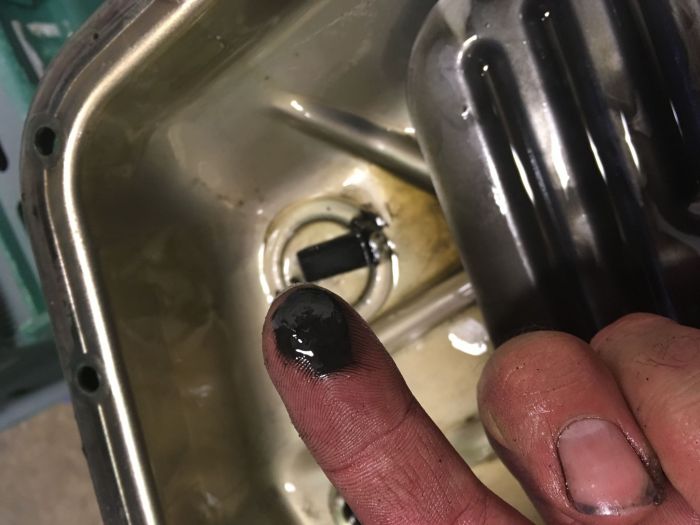
So the saga continues:
|
||||||||||
|
| holidaychicken Member Since: 06 Nov 2013 Location: Kent Posts: 1086
|
Not read the whole thread but when i did mine I had RRPhil inspect the valve body, I replaced all the internals that usually wear from the service kit, bearings and seals and any suspect clutch plates and had the TC refurbished by sussex auto parts.
|
||
|

|
|
| All times are GMT + 1 Hour |
< Previous Topic | Next Topic > |
Posting Rules
|
Site Copyright © 2006-2025 Futuranet Ltd & Martin Lewis
![]()
