 | Home > Technical (L322) > Transfer box motor? |
 
|
|
|
| RRPhil Member Since: 22 Aug 2011 Location: Blackburn, Lancashire Posts: 1000 
|
The Range Rover never suffered from the �split drum� issue as, by 2002, ZF were fitting the stiffened A-clutch drum to all 5HP24s
Phil Admin note: this post has had its images recovered from a money grabbing photo hosting site and reinstated |
||||||
|
| tymh Member Since: 21 Apr 2014 Location: Garstang Posts: 312  
|
Thanks for that - at least it puts my mind at rest with regard to the fail safe issue! |
||
|
| Joe90 Member Since: 29 Apr 2010 Location: Hampshire Posts: 6419 
|
Browsing through RAVE this evening (as you do!) I noticed a section for replacing the "fuse" for the Transfer Box, which is located in the engine compartment below the Transfer Box ECU. From the circuit diagram this is a 50 amp jobby. Could this have anything to do with it not switching from low to high ?
|
||
|
| tymh Member Since: 21 Apr 2014 Location: Garstang Posts: 312  
|
Thanks Joe - now it's in high range I'm loathed to try this as I don't want it stuck in low again!
|
||
|
| povh Member Since: 16 Oct 2015 Location: Ljubljana Posts: 4  
|
Sorry for link to another forum
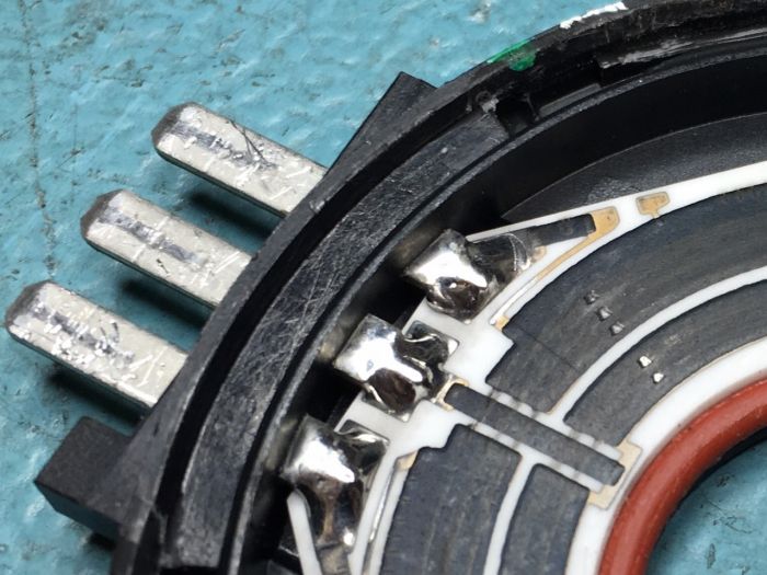
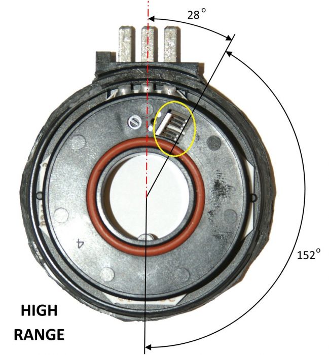
This problem was not detected either with ohm-meter or oscilloscope. So I just bent all five sliders for about 1mm so they are running on fresh track of the graphite and sensor should be OK for another 10 years. Price : 0 Time: 1h It is working for me for some time now.[/img] Last edited by povh on 23rd Feb 2016 2:44pm. Edited 1 time in total |
||||
|
| stan Site Moderator Member Since: 13 Jul 2010 Location: a moderate moderated moderator moderating moderately in moderation Posts: 35650 
|
rather than linking to another forum , can you post your solution here... ... - .- -.
|
||
|
| Meerbusch Member Since: 16 May 2012 Location: Zürich (CH) + Düsseldorf (D) Posts: 325  
|
sorry, had posted the link, my english was not able to read the rules.... |
||
|
| povh Member Since: 16 Oct 2015 Location: Ljubljana Posts: 4  
|
It is not enough to clean the potentiometer as it is not really dirty. You have to modify sliding pins in the potentiometer. If you look the picture you will see where is a problem ( and sollution |
||
|
| Jimmy C Member Since: 05 Feb 2015 Location: midlands Posts: 115  
|
not being mechanically minded can you arrow the 5 sliders on the picture that need bending as looking at the picture i have no idea. |
||
|
| povh Member Since: 16 Oct 2015 Location: Ljubljana Posts: 4  
|
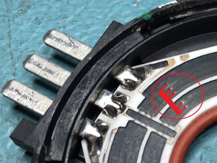
On this pictuere you can see sliders,
They are running on graphite track and you can see holes where sliders lay most of the time. Sliders are not on the pic so I painted them with red color:
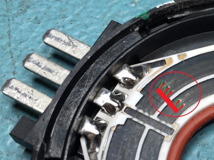
I bent sliders like marked with green:
If you want to open potentiometer you have to cut glued part with sharp knife and slowly open cover with flat screwdriver. Bending slider pins is very precise work so you can destroy them in a second, so be careful! Hope it is more clear now |
||||||||
|
| Jimmy C Member Since: 05 Feb 2015 Location: midlands Posts: 115  
|
Thanks, not sure if im willing to try as can be a little heavy handed |
||
|
| mr_spock Member Since: 07 Apr 2016 Location: Welwyn, Hertfordshire Posts: 311  
|
I suspect I may have this problem. Has anyone tried something like this to repair the track:
|
||
|
| verydisco Member Since: 10 Dec 2009 Location: UK/US Posts: 2952  
|
Hi Gang,
|
||
|
| mr_spock Member Since: 07 Apr 2016 Location: Welwyn, Hertfordshire Posts: 311  
|
That's what I did in the end. |
||
|
 
|
|
| All times are GMT + 1 Hour |
< Previous Topic | Next Topic > |
Posting Rules
|
Site Copyright © 2006-2025 Futuranet Ltd & Martin Lewis
![]()


