Advertise on fullfatrr.com »

Home > Maintenance & Mods (L405) > ACE pipe replacement / heater cross over pipes (no lift)
Post Reply  Down to end
Page 1 of 1
Print this entire topic · 
fisha


Member Since: 25 Sep 2009
Location: Scotland
Posts: 1333

2015 Range Rover Autobiography SDV8 Aruba
ACE pipe replacement / heater cross over pipes (no lift)

Now the job is done, I'll post up some thoughts / observations / tips / photos that can might help others if your trying this as a DIY job.

This isn't a full on how-to guide as many steps are missed. Its just comments on how I did it as a reference, so that it may help others who want to try the same, but may not have access to post lifts etc. ( There is no doubt a lift would have helped. Dont think I've done so many sit-ups from crawling about under the car ! )

Many thanks go to Pete (Haylands) and Mikey (plus anyone else whos posted about replacing ACE pipes on forums) for their help / thoughts and advice on doing the job, genuinely couldn't have done it without their prior knowledge / experience being offered.

Before tackling the job, have a read around some of the other threads such as:

https://www.fullfatrr.com/forum/topic67828.html
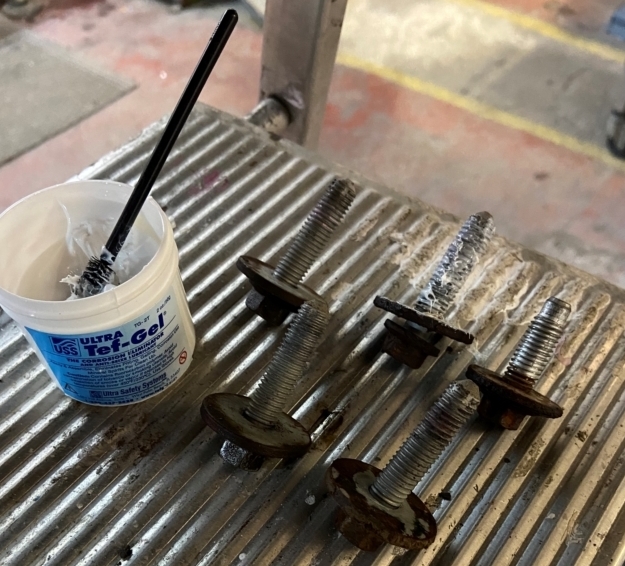
Note the prep of the new pipes - i did the same.


Tools I used / needed / found useful

2 basic trolley jacks - not workshop jacks with the handles attached, you need the jacks to be able to go under the car.
2 axle stands
Decent 6 sided socket sets.
Decent torx socket sets
Decent spanners
Bolt head extractors like these as some sill bolts were tight / stripped

Large subframe bolts - 18mm
Medium subframe bolts - 15mm
There was also 13mm bolts too ( like the collet holding the pipes into the valve block )
Pipe brackets, sill protections - typically 10mm
Pipe unions were 18mm and 20mm iirc.

Workarea: For the rear pipe, I needed about 2m of space to the LHS of the car to allow me to feed the pipe into the wheelarch area whilst the rest of the pipe stuck out to the left.

Initial prep steps:
Put it in off road height, and then remove the sill covers on both sides. ( take the end sections off, then the outer cover, then the inner cover.
Take the exhaust off from the mid-section backwards. It comes off easier if you undo all the hangers at the rear, and then support it with a jack to keep it level. You can hit it out by using a ball joint splitter fork inserted across the bracket joining the 2 pipes together just a couple of inches downstream of where you are disconnecting it.

Whilst its on the ground, undo / loosen / refit the subframe bolts. Far better to get these loose whilst its on the ground and you can put force into it without fear of it tipping. Clean the rust off with a wire brush, and tap the socket (18mm ) on initially to ensure it fits all the way home so you get the max grip possible on the bolt head.

Do this by hand using a breaker bar. Get it to break away a bit and then re-tighten slightly, loosen more, tighten slightly, repeat.( Think of a 2-steps forward, 1 step back approach ). The bolt will quick lose its tension / tightness and easily come out with a ratchet rather than breaker bar on the socket.

Getting it high enough off the ground

Put it in off road height, the disconnect the fuses in the rear fuse box by the battery. I took out the 4 that were labelled with the air suspension sign


There was a 60A, 15A, 10A and 5A on mine.

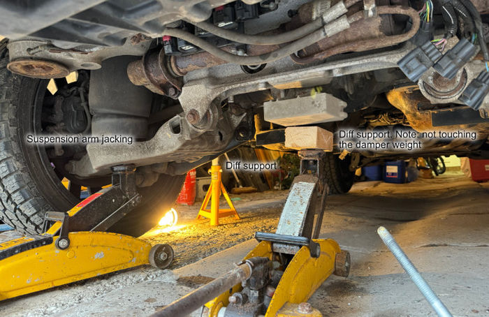
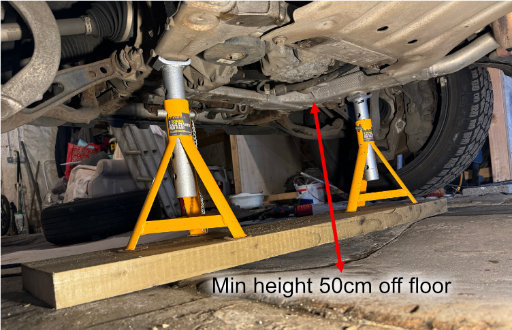
Next put the 2 trolley jacks under the rear suspension arms. My halfords jacks have a round platform which fits nicely into the circle moulding that the airbag mount pokes through. Then jack up the car by the arms, and place the axle stands under the sill jack points. Get it high enough that when you let down the jacks, the wheels are left hanging in the air with the suspension fully extended.


As an example, you can see the general setup here: Axle stand on the sill, trolley jack supporting the diff/subframe, and it also shows how the jack I used slotted into the underside of the suspension arm.


Once up in the air, wheels off and I disconnected the airbags. Did this by undoing the pipe into the bag, and letting it hiss slowly to let the air out.


Lowering the subframe

You can now lower the subframe and hang it on its mounting bolts.

Prep: remove the heatshields to expose the propshaft, and then undo the 2 bolts that hold the centre carrier to the body. This allows enough flex in the prop to lower the subframe.

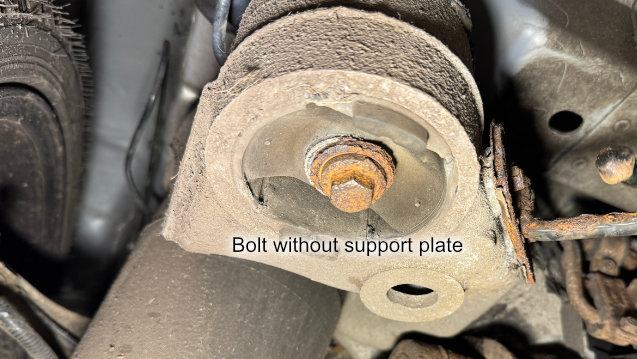
Each corner of the subframe has 2 plates top and bottom ... you dont need the lower plates present to hang the subframe - the bolts are big enough:


To remove them, I wound out 4 corners and lowered the frame by about 1" all round. Then placed a jack in the middle that supported the diff.

Then for each bolt in turn, I completely removed it, took out the top and bottom plates, then put the bolt back in a few turns so that there was enough grip on the threads to hold the weight. The trolley jack on the diff can help support / raise / lower as needed. At the end of this, the subframe will be hanging on the bolts leaving ~75-80mm gap all round.

Now is a good time to clean up / prep the chassis.
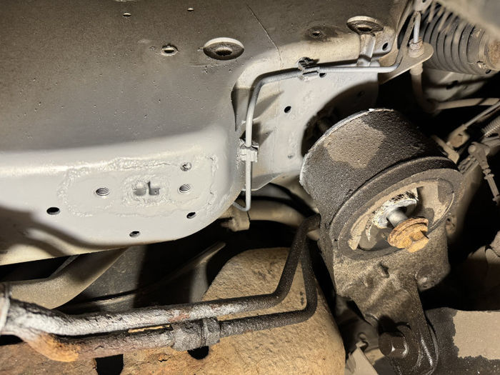
Depending on your climate, expect corrosion of the chassis. The plates are steel, mounted directly against alu, which will only end in corrosion of the alu. Mine was there, but not fatal. For example, this was the worst of the corners:


In fact, it was so bad, that the white alu oxide had built up with so much pressure, that the flat plate was bent out of the shape at the edges.

Cleaned up by scraping/chipping off, buff down with sand paper, cleaned and etch primed:


Later Dinitrol'ed, but see Pete's thread for more on that.


Further lowering of the subframe.

You can drop the subframe on 1 side further to give you another couple of inches of room ( invaluable ).

With the trolley jack supporting the diff, undo the LHS bolts completely, then lower the jack down. This will drop the LHS of the subframe where the pipes go over.
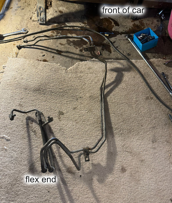
The pipes removal.
Nothing special about this. Remove them. Undo the rubber mounting bolts ( if they haven't already sheared ). and disconnect each end and waggle out to remove. Mine cam out in a 1 go by coming forwards.

In hindsight, just chop the blooming thing into sections and remove the sections. You're replacing it, so who cares!

Fitting new pipes

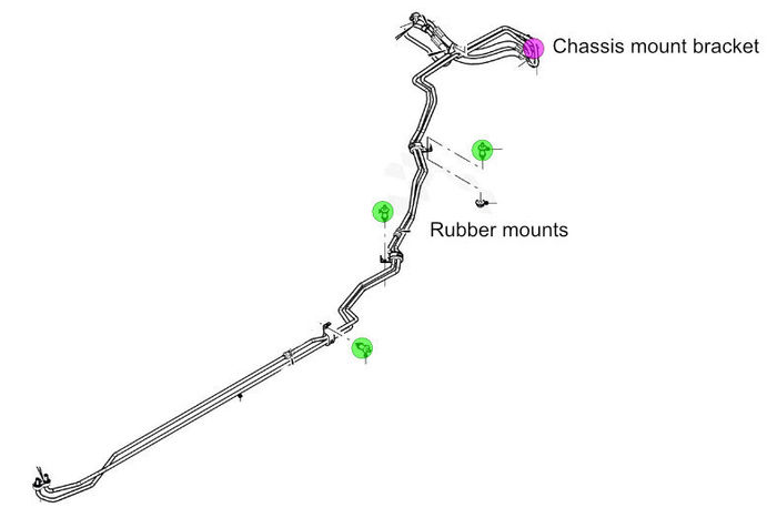
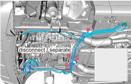
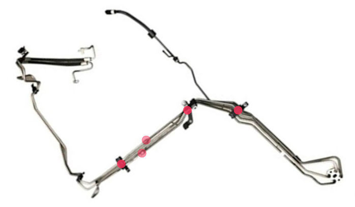
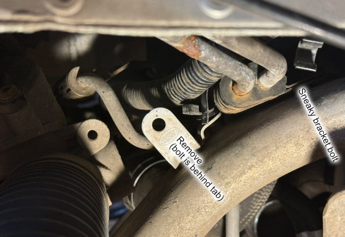
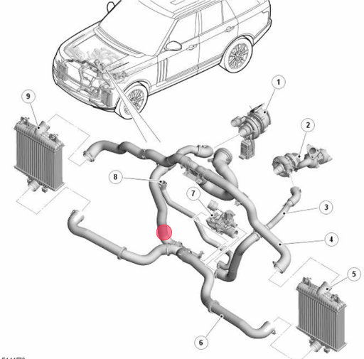
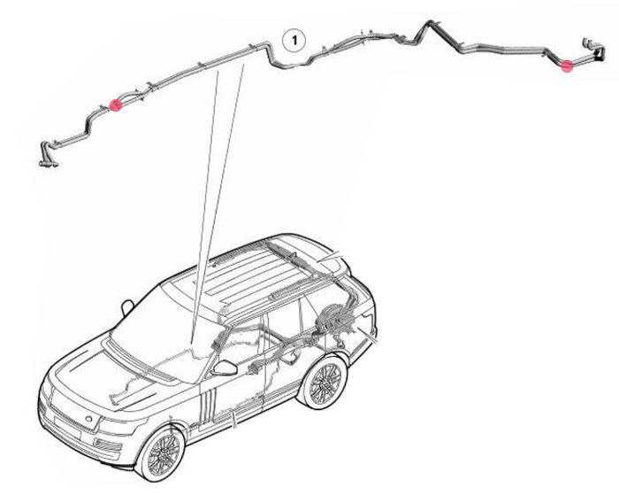
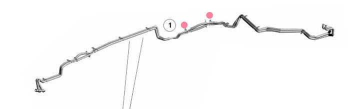
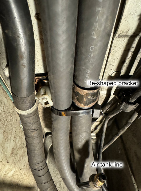
Prep: I took off the bracket at the rear end where the flex hoses start. This allowed the pipes to move around more when fitting them in. Bracket can be added back in once the pipes are roughly in place. ( pink dot on image )

You will need new rubber mounts ( LR038632 )- just buy some - all 3 of mine were wasted - ebay was cheapest for me at the time, but they are rip-roaringly expensive for what they are. ( green dots )


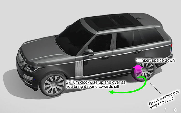
Finally, fitting the pipe ... hoorah, at last. OK, I'll try and describe this as best I can:

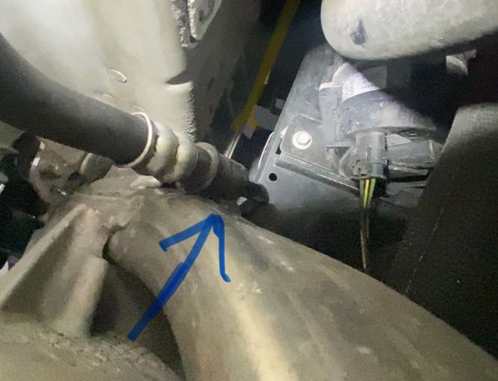
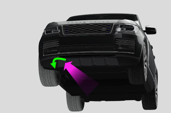
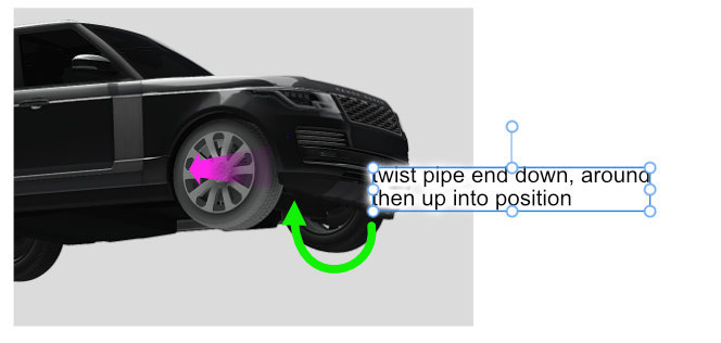
With the pipes almost upside down to how they fit on the car, feed the flex pipes into the space from the rough angle as shown by the arrow:


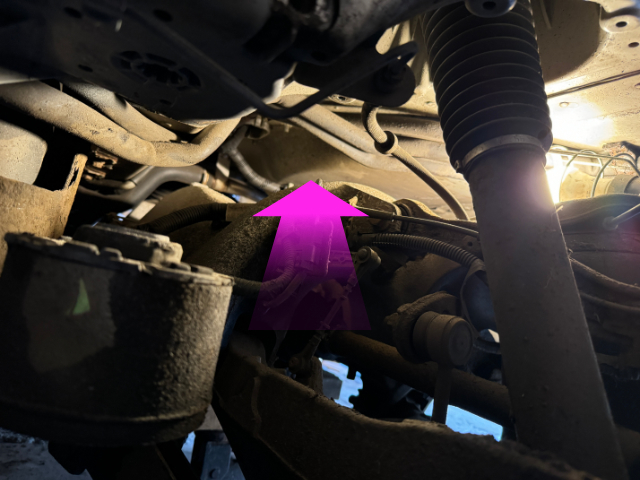
IIRC, I led with the flex hoses, and the rest of the length of pipes were almost at 90° out to to the side of the car. Then as you manipulate the flex ends up and over, I twisted the pipe work clockwise and brought the front ends of the pipes over towards the line of the sills. Think of it a little like cork-screwing the pipework in.


No two ways around it, it was a faff as the front end of the pipe kept getting caught on junk in the garage ( hence my suggestion for cleare space ), and the flex hoses kept getting caught on stuff around the subframe.

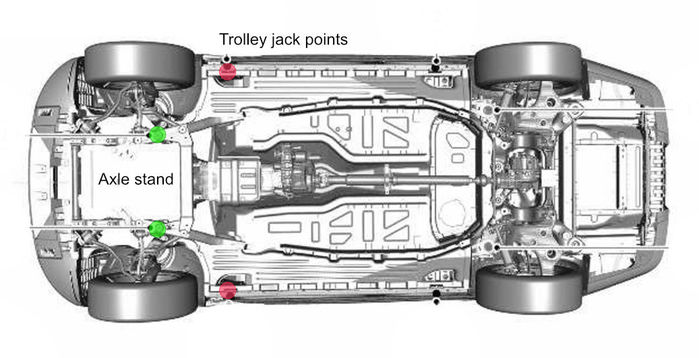
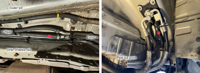
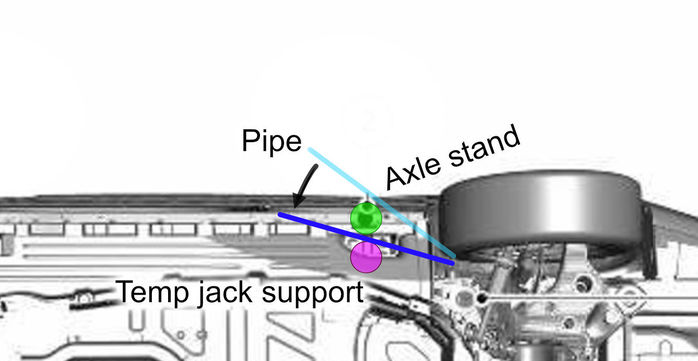
but what about the axle stand ? You have to get the pipes from outside the axle stand to inside it. To do this, I used the spare trolley jack and a block of wood to temperarily support the car, remove the axle stand, put the pipe past, and then re-instate the axle stand. The temp support site I used was the flat chassis casting ( pink dot ) just inside of the sill jack point ( green dot ).


From there, its home run time ... pipes and mounts can all be connected up.

Putting it all back together

Pretty much a case of reversing the procedure.

Prep: Deal with the subframe support plates. Pete powder coated his and put silicon sheet between the plate the chassis. I cleaned mine up with a wire brush on a drill, primed, painted and dinitrol'ed mine, and also put the silicon sheet between the upper plate and chassis. I used the plate as a template to cut around.


*** Follow up edit: ***

Since driving the car after all this work, I've noticed a marked improvement to the car in terms of road noise / vibration within the cabin. It wasn't just a case of going back to how it used to be before the work, it was markedly better and quieter and smoother feeling. I've spoken with Pete, and he came to the same conclusion I did, that the silicon pads must be doing a good job of isolating vibration from the subframe travelling into the chassis.

So I cant recommend enough to add the pads between the subframe plates and the chassis when doing this work.

***

Re-fit the subframe with NEW bolts. Hand tightened with the ratchet and breaker bars. I was advised to no go as high torqued as per the workshop manual. I'll let you be the judge of it for yourself at that point.

To get it back on its feet, I reconnected the airlines to the airbags, re-fitted the fuses, fitted the wheels and put the 2 trolley jacks back under the arms and jacked up the arms enough that the wheels where off the ground again. Then started the car, selected off road height, and the bags reinflated, lifted up the rear end off the axle stands supporting the sills. Removed the axle stands, and then lowered the jacks down to let the wheels sit on the ground.

Re-Alignment

There is play in the subframe bolts and supports which means the it can be re-mounted at a different alignment to what it was before being dropped, the workshop manual mentions getting the alignment down after this sort of work.

I cant remember exactly, and didn't take pictures, but was conscious of this during refit. I think I was able to spot that bolts, bushes and plates weren't lining up to the same wear points on first attempt.

To adjust, I just loosened the subframe bolts and manipulated the subframe into its old alignment and then re-tightened.

In hindsight, might be worth making indelible marks on pieces before removal to show alignments.
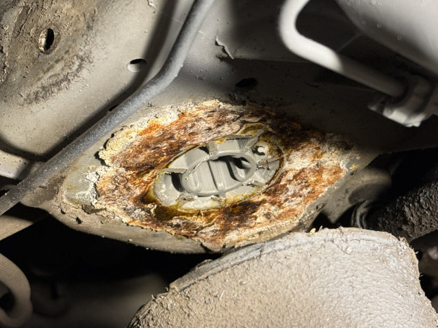


The diff plug

When you're putting it all back together, now is a really really really good time to change the oil int he rear diff.

I tried to do this last year, and failed because I stripped the plug socket. Because you have the exhaust off doing all this work, you can get much better access to the fill plug. I took the opporunity to extract the plug, fit a new one, and refill. I suggest you do the same.

The pic below shows the plug finally released after much heat from a MAP gas torch and hammering.
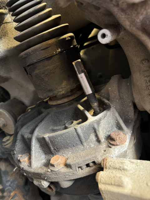

Click image to enlarge
 V8 or else ...

Last edited by fisha on 19th Sep 2024 4:35pm. Edited 9 times in total

Post #700121 14th Sep 2024 4:46pm
View user's profile Send private message View poster's gallery Reply with quote
fisha


Member Since: 25 Sep 2009
Location: Scotland
Posts: 1333

2015 Range Rover Autobiography SDV8 Aruba

Front pipes - Easier than the rear ones. The front end of mine was in far better shape corrosion wise compared to the rear. Only corrosion on the pipes were at the valve block area, where water and muck had accumulated around the valve block.

Prep:
Sills off
Undertrays off.
Wheel arch liners off ( also take off the plastic lower section which sits just above the driveshaft and steering arms )
I did not need to disconnect any suspension arms.

Jacking up the car - minimum height

Into off road height, then disconnect the 4 rear fuses.
Jack up the car by the sill jack points
Axle stands on the front subframe:


From hindsight, you need to get around 50cm in height between the subframe and the floor. I lucked out in that my garage is an old milking barn with a worn out dip in the middle from cattle ( hence the plank of wood to level things out . My jacked height was less than 50cm, was boosted by the dip, but if your floor is flat then 50cm should be enough.


Splitting / separating the pipes / Prep for removal

You need to separate the pipes, and think of them in 3 sections.

a) one that runs from the valve block straight forward to the front of the LHS wheel arch.
b) pipes that run from the valve block to the rear area of the RHS wheel arch
c) pipes that run from the rear RHS wheel arch forward to the anti-roll bar

Easier to split the pipes in situ by removing all the rubber bracket clamps and undoing the 2 unions in the pipes ( red dots ) and also any places the pipes are mounted to the chassis by the rubber mounts that were also on the rear.


Also do the same with the new pipe to split it up:


To disconnect a) pipe running straight forward

This ends in a push fit connection. Its discussed in this thread here and looks like:


If you're replacing the pipe, there is little point being merciful on the connector. I tried to no avail to insert collets and similar to release the holding barbs. In the end I attacked it with a screwdrive and broke all the tabs off. It seperated no problem after that.

Best access to be able to do that is to remove the LHS air filter housing and you can then see straight down from the engine bay to the connector with decent space to wield a large screwdriver into the gaps and twist snap the connector pieces off.

For the other push fit connector at the rear of the RHS wheel arch, see the thread linked. Basically you need to push down hard on the black collar, and then pull apart the pipes. I didn't have the tool illustrated in the thread, but used a vehicle trim removal tool filed to the right gap along with a screwdriver for leverage.

Disconnecting the front pipe section

For me, I undid the bolts mounting the roll bar to the chassis enough that I could remove the pipe connectors from the unit. Then completely undid the bolts and let the whole unit hang by its arms off the drop links. I figured that if the drop links could try and counter the lean of the car, they would take the weight of the unit. You could support it if you want, I couldn't be bothered.

Also, there is a sneaky bracket mount on the top of the chassis leg to remove, and its also 100% worth removing the metal tab ( which is used to hold the lower plastic guard section of the wheel liner. ). If you look in from the front of the RHS wheel arch, you see the tab pictured below:


Also disconnect the turbo hose from change over valve thing. The pipes loop over this, and its far easier to just undo the turbo hose to create a gap for the ace pipes to fit through. red dot below


Removing the front section of pipe

Its tight and fiddly, but it will get out. As mentioned in another thread, you need to make use of the flex in the pipe to wrangle it about.
Probably best to describe the general movements of it.
In essense it comes out the front in a circular motion along the route of the pipe itself.
To start, the flex hose end comes downward and towards the LHS.
You can then free the other end out into the wheelarch area.
As you try and continue to pull the pipe around, the flex hoses keep coming down and to the LHS.
As the flex hoses get towards the floor, I then pulled the flex end along the floor towards the front of the car.
This point is why you need the minimum height listed above. I only just had enough height to tuck the flex end under itself towards the front.
Once rotated, the rest of the pipe came out.

A bit hard to show, but this is how the pipe came out and lay on the floor after. I took a pic to give me a reference point to start the refit. You can see its upside down and wrong way round.

Click image to enlarge


Removing the rest of the pipe

Fairly simple. Because you've disconnected the bracket nearest the valve block, the pipes can easily be pulled backwards towards the valve block and out.


Refit is reversal of removal

I laid the new pipe on the floor as per the picture above as the starting point.

Inserted and begin the turn to make the ends follow the chassis rail towards the back:


then as you're coming further back, twist the flex end down and under to rotate the pipes and continue to feed through


The back half of the pipes just fed in the same way they came out.
Only thing to note is that because you've undone the brackets that hold the pipes in alignment, just make sure that the 3 pieces of pipe that run across the cross member are in the correct order/orientation. I had them crossed over, which mean the brackets wouldn't fit or align. Easy sorted, but just something to note.


Refill the system
For me, i filled up the reservoir, started the engine and filled it back up
Took it for a drive where it complained of leaning too much almost instantly.
Refilled again and out for a short drive, repeat.
Took 3 fills and drives to fill and sort itself to the point of no error.
I'll periodically check the level over the next while.


I didn't open the bleed nipples of either front or back units.
I may revisit that though. As when I initially reverse out of the drive, I get a slight knocking sound initially which disappears once moving properly. It kind of sounds like a CV joint clicking, or the fuel tank slap sound.

There is maybe a little air trapped, and it needs to run to clear. ( might find a local roundabout and go round it a few times so that the system works in one direction for a sustained period ) V8 or else ...

Last edited by fisha on 15th Sep 2024 12:23am. Edited 4 times in total

Post #700122 14th Sep 2024 4:46pm
View user's profile Send private message View poster's gallery Reply with quote
fisha


Member Since: 25 Sep 2009
Location: Scotland
Posts: 1333

2015 Range Rover Autobiography SDV8 Aruba

Heater cross over pipes

The heater pipes for the rear climate control run down the RHS sill area and then up, over and across the rear subframe till they reach the back section of the rear LHS wheel arch. The pipe is a pointless, only could have been designed on a computer combination of metal pipe and rubber hose.

Its known to corrode and leak over time. So whilst the subframe was lowered to do the rear ACE pipes, I took the opportunity to replace the heater pipe too. I replaced between the 2 red dots with a single run of heater hose ( standard 16mm stuff ). I bought 10m which was waaaaay more than plenty Whistle .


Chassis pipe support brackets.

The pipe is held in place by brackets which bolt to various points along its run. For the most part these aren't too hard to access / remove / undo. you can reach up around the subframe for the cross over points, and you can undo the airline to the air tank and drop that out exposing the whole sill. ( I'm amazed at how little the air tank weighs )

A problem with removing the original setup is that there are 2 brackets which hold the pipe to the inner wall of the chassis rail right next to where the fuel tank is (red dots). To access the bracket bolts, you'd need to drop the fuel tank out.


No chance of me doing that.

So instead, I used a bread knife ( cause no other knife works better in this situation ... really) to cut the rubber section of hoses between the brackets dotted above, and I then used excessive force to pull break the pipes and brackets to free them up. One way or another, that pipe was coming out, and it did Rolling with laughter . Afterwards, what was left of the brackets was flattend down out of the way.

I cut the wheel arch section of the existing pipes just before they turned in towards the subframe ( see below ).
Under the sill, I simply disconnected the rubber hose at the forward end of the sill from the metal pipe coming from the front wheel arch area. I kept the clamps to reuse.

Fitting new hoses

I fed the new hose through along the same run as the previous pipe. Started at the rear LHS wheel arch and worked forward.
I did one hose at a time, and marked each one with different coloured electrical tape at each end so I could re-match up the correct pipes. The image below shows which pipe matches which by the red dots.


New brackets
For holding the hoses over the subframe, I just used big wide zip ties placed at suitable points holding them to other things ( like the air-con pipes, and the electrical loom going into the boot floor.

Where the hoses run along the sill, I reused the brackets that held the 2 metal pipes, and re-shaped them to hold 1 hose, and zip-tied the other hose to it:

Click image to enlarge


Refilling the coolant.

Covered here V8 or else ...

Last edited by fisha on 15th Sep 2024 12:28am. Edited 3 times in total

Post #700123 14th Sep 2024 4:47pm
View user's profile Send private message View poster's gallery Reply with quote
Haylands


Member Since: 04 Mar 2014
Location: East Yorkshire
Posts: 8130

England 2014 Range Rover Autobiography SDV8 Loire Blue

Excellent write up, my only 2p is to use TefGel or similar on all the bolts that bolt into the alloy monocoque, and as fisha says don't torque them up to the ridiculous torque posted in the WM, that's for a brand new part on a new car.

https://www.tefgel.com/contain.php?param=tefgel_infor


 Pete

__________________________________________________
2014 L405 Autobiography SDV8 4.4 Loire Blue Ebony interior
2011 L322 Vogue SE 4.4 TDV8 Baltic Blue. Parchment over Navy Interior. Sold
2012 L322 Autobiography 5.0 Supercharged Ipanema Sand, Jet Interior. Sold
2002 L322 Vogue 4.4 V8 Epson Green, Ivory over Aspen Interior (Fatty Offroader) Sold
-Click for Project Fatty off roader-

Post #700129 14th Sep 2024 11:19pm
View user's profile Send private message View poster's gallery Reply with quote
fisha


Member Since: 25 Sep 2009
Location: Scotland
Posts: 1333

2015 Range Rover Autobiography SDV8 Aruba

Thanks Pete.

On reflection, I still think the process is overly convoluted, and could be far easier if the steel pipes were replaced with hydraulic hoses.

There is nothing fancy about the ends of the pipe. They are push fittings for which I imagine any reasonable hydraulic supplier would be able to re-create, and then make lengths of hose to suit. That plus a couple of suitably made support brackets, and you'd be laughing.

In fact, one post on the RRsport ( I think ) forum talks about doing similar that for a fraction of the price of the steel pipes. ( i.e. less than £100 for the rear pipes )

Whilst its not something I hope I'll need to do now, its still bugging me, and I might ask around. V8 or else ...

Post #700131 14th Sep 2024 11:33pm
View user's profile Send private message View poster's gallery Post Reply
Post Reply  Back to top
Page 1 of 1
All times are GMT + 1 Hour

Jump to  
Previous Topic | Next Topic >
Posting Rules
You cannot post new topics in this forum
You cannot reply to topics in this forum
You cannot edit your posts in this forum
You cannot delete your posts in this forum
You cannot vote in polls in this forum


Site Copyright © 2006-2024 Futuranet Ltd & Martin Lewis
fullfatrr.com RSS Feed - All Forums


Switch to Mobile site