| L322 Throttle Body Resistance and Voltages Typical Values? | |
I am looking for input on what "normal" resistance measurements and voltage measurements are for the 4.2 SC throttle body position sensor. A long with a variety of other DTCs, i am slowly verifying function of each DTC.
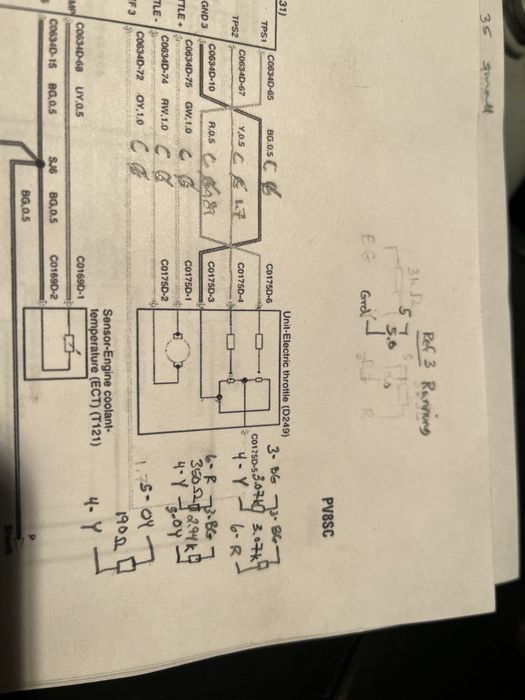
Specifically I'd like to compare my resistances and voltage readings to a working throttle body position sensor. Here is a picture of my resistance measurements.
Measured resistances across position sensors as I rotated buttery fly in throttle body. Oddly, the resistances don't change (i figured they would, since my understanding is they are potentiometers). The image below shows the resistance values that I measure.Does anyone know these or have an actual diagram showing what the resistors are inside the position sensor?
 | | Click image to enlarge |
This is what I have done thus far to test:
1) Backprobed Throttle body connector: while vehicle is idling, Checked 5 volt reference signal to ground, yes it is 5 vDC,
2) Backprobed Throttle body connector: while vehicle is Idling, Measured Sensor 1 voltage at 0.85 VDC, measured sensor 2 voltage at 1.7 VDC. Is this a normal value for closed throttle body?
3) disconnected throttle body from vehicle and connected throttle body to an external 5 VDC power supply, rotated butteryfly to see if voltage changed. It does, but i am not sure if it is changing like it is "supposed to". From closed to vertical, voltage goes from 0.85 to 4, and 1.7 to 4.3 on position sensor 1 and 2 respectively.
Any additional info from the forum would be helpful.
Thanks
Jeff
|


![]()

